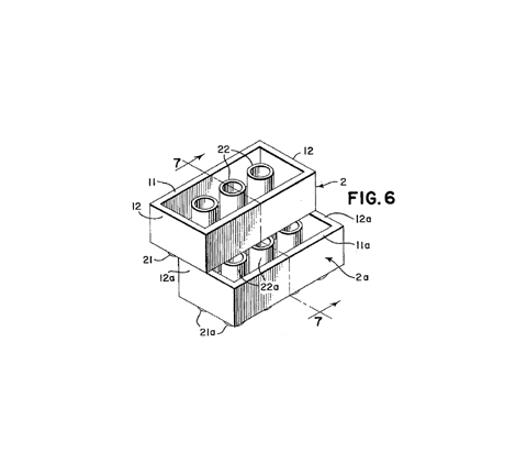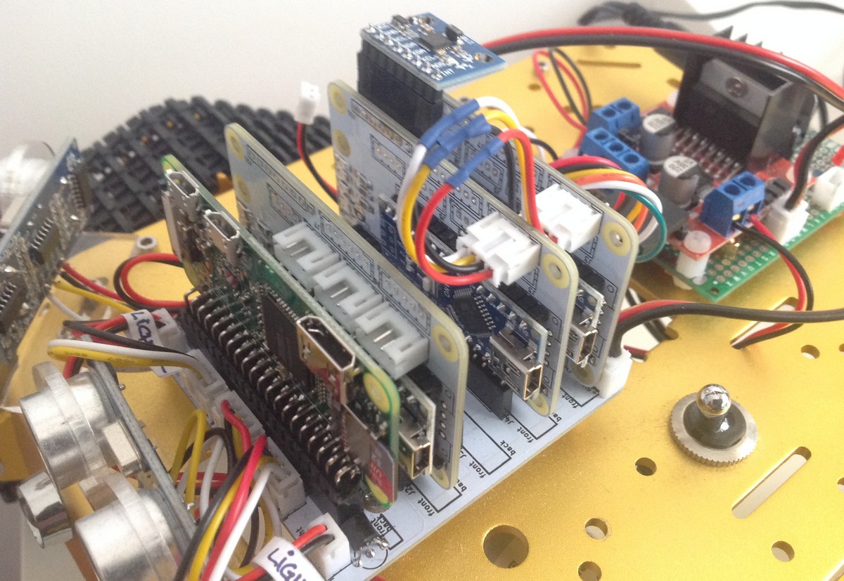
The boblock is the mechanism to open the HW to a collaborative development. A functionality that requires new HW can be added with an adhoc module, developed with the most convenient HW and SW technology, and connected into the system by plugging the moudle into the WBUS. In this sense, the boblock is like a LEGO block that allows building variants of the project by adding or removing pieces. At the current moment of the project, 3 of these blocks are available, all of them running over the same HW: the one of the motor controller for managing the H-Bridge and encoders, the one of the sensors for reading an array of proximity HC-SR04, and that of the gyroscope. It would be desirable to make available a laser-based proximity sensor or to integrate a LIDAR.
The WBUS is directly connected to the Arduino Nano pins so the electrical specifications are the ones of the Arduino. The WBUS pin-out is as follows:
| PIN | Description |
|---|---|
| 1 | 5Vcc in |
| 2 | I2C SDA |
| 3 | I2C SCL |
| 4 | GND |
| 5 | WA7 |
| 6 | WA3 |
| 7 | WA2 |
| 8 | WIO1 |
| 9 | WIO2 |
| 10 | GND |
| 11 | WD9 |
| 12 | WD8 |
| 13 | WD7 |
| 14 | WD6 |
| 15 | WD5 |
| 16 | WD4 |
| 17 | WD3 |
| 18 | WD2 |
| 19 | GND |
| 20 | GND |
Version 1 of the boblock is a carrier of an Arduino Nano. The manufacturing files are available at GitHub for download. These files are tested with SeeedStudio. In that case all you need to do is upload the zip files exactly as you get them from GitHub.
The SW varies depending on whether it works as motor, sensor or gyroscope. You need to download the corresponding SW of the module you want to run and program the cars using the Arduino IDE environment.

The boblock is powered by the 5V coming from the WBUS. A 12V source is provided for testing and development purposes, however it is not necessary when choosing the 5V source. To operate at 5V you need to solder the jumper labeled "+ 5V_Arduino” located at the rear.
For updates and debugging you can connect the Arduino IDE environment while the vehicle is powered. This is possible thanks to the automatic power source selection done by the Arduino's HW and to the schottky diode (D4) that prevents back currents from the board to the WBUS.
The bill of material is the following:
| Ref. | Qty | Description |
|---|---|---|
| PCB | 1 | GitHub |
| J2 | 1 | 20 pin header angle |
| R1 .. 3 | 3 | Resistor 1K SMD 1206 |
| D1 .. 3 | 3 | LED KP-3216SRC SMD 1206 |
| D4 | 1 | Schottky diode 20V 0.5A SOD123 |
The resistors and led diodes are optional.
By default, the I2C of the Arduino is isolated from the WBUS. For the motor module you need to solder the jumpers located on the rear side of the card that are labeled SCL and SDA.
The module connected to the H-Bridge and to the encoders throught the connectors 3, 4 y 5 in the mother board that are linked to the slot labeled motor.


