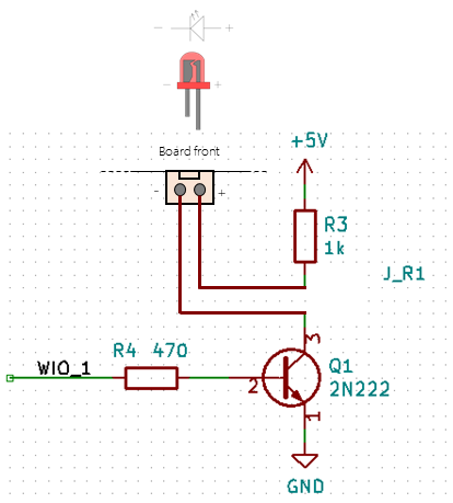
Connectors 9and 10on the motherboard are digital outputs that are connected, respectively, to WBUS's pins WIO2 and WIO1 through the circuit shown in the figure:

WIO1 and WIO2 are connected to pins 16 and 18 of the Rasberry's 40-pin header, and these to pins GPIO23 and GPIO24, respectively.
The purpose of this circuit shown in the picture is to protect the Raspberry's GPIO pins, adapt the voltage from 3.3 to 5 Volts and provide additional current. Remember that a Raspberry can supply a maximum of 16mA per pin with the total current from all pins not exceeding 50mA.
The type of transistor and the value of the resistors described can be changed. For the proposed configuration with a 2N2222 transistor, each connector sources 5V and up to 800mA.
WBUS lines WIO1 and WIO2 are also connected to the rest of the slots in anticipation that they are necessary by some other modules, other than boblock 1.0, such as a two-motor robot arm controller.
| Ref. | Qty | Description |
|---|---|---|
| Q1 & Q2 | 2 | Transistor 2N222 NPN DIP |
| R3 & R5 | 2 | Resistor 1K 1/4W 5% DIP |
| R4 & R6 | 2 | Resistor 470 Ohm 1/4W 5% DIP |


