Orientation and position estimate
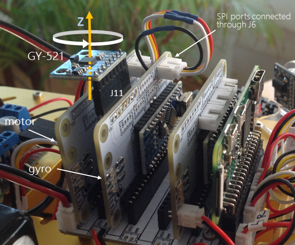
The slot in the motherboard that is next to the motor one and tagged as Gyro is meant to hold the gyroscope. Both modules sit side by side for the gyroscope works as an add-on of the motor module and both are linked through connector J6 that is an extension of the Arduino’s SPI port.
The gyroscope module is a controller of a GY-521 that is inserted into the J11 connector. In the case of the gyro module, the I2C port is used for communication with the GY-521 and not for interfacing other modules via the WBUS, as is the general case.

The GY-521 module is a breakout board for the MPU-6050 manufactured by InvenSense, today part of TDK. To understand the contribution of this module to the project, it is necessary to know that the MPU-6050 is what is known as an IMU (inertial measurement unit), and as its name indicates what these devices measure is inertia. An IMU actually measures electric changes due to the piezoelectric effect, which is nothing other than changes in the conductivity caused by the movement of the crystals or mechanical structures built into the chip, as a consequence of the inertial forces produced when the vehicle moves. Ultimately, IMUs measure (inertial) forces, and from there other units such as acceleration are derived.
I think it is worth giving this explanation because when one reads that the GY-521 provides acceleration values, one might think of integrating these values to obtain the speed, and integrating the speed to obtain the displacement. However, the only thing we would be doing is integrating noise, since the speed is obtained from something that is not acceleration but a value relative to an inertial force. The reality is that the accelerometer does not provide any information that we can use.
However, the accelerometer serves to compensate the drift that the gyroscope suffers due to the fact that the angular velocity sensed by a gyroscope results from the integration of an angular acceleration that is affected by noise, and the integration of noise over time turns into drift. In summary, the accelerometer information is worth, only, to correct that of the gyroscope. This is the principle of Sensor Fusion technology that combines the information from a variety of sensors, such accelerometers, to obtain more accurate rotation information. The clearest explanation I have found of the contribution of the accelerometer to the gyro measurement is this talk at GoogleTechTalks by David Sachs.
Out of the 6 values the GY-521 senses (3-axis gyro and 3-axis accelerometer) only the 3 related to rotation are of some use. And out of these 3 only the one of the perpendicular axis matters given that the vehicle moves in a plane. In sum, the contribution of the gyroscope module to the project is the measurement of rotations on the Z axis. This information is what allows the vehicle to perform precise rotations and to know its orientation, not absolute but, relative to the position the vehicle started moving.
SW
The software for this module is mostly code from Electronic Cats' MPU6050 Arduino Library which in turn comes from Jeff Rowberg's project published at GitHub.
From this code I have taken the following files:
- src\helper_3dmath.h
- src\I2Cdev.cpp
- src\I2Cdev.h
- src\MPU6050.cpp
- src\MPU6050.h
- src\PU6050_6Axis_MotionApps20.h
And modified
- examples\MPU6050_DMP6\MPU6050_DMP6.ino
to add an API through Arduino's SPI port.
HW
The gyroscope module works with a GY-521 inserted into connector J11. The GY-571 needs to be set horizontally so that the gyro's Z axis is perpendicular to the vehicle.
The I2C of the Arduino must remain unconnected to the WBUS, for that reason, do not solder the jumpers SCL and SDA on the rear side but the two located on the front that are next to the J4 connector. This way the I2C of the Arduino is connected to J11 and from there to the GY-521.
| Name | Qty | Where |
|---|---|---|
| GY-521 MPU-6050 breakout board | 1 | Banggood AliExpress |


