The following are the vehicle mounting instructions. Once completed, and after installing the software, you get a vehicle that is controlled from a WEB application running on a mobile.
The assembly is divided to:
• Chassis
• Power module
• Control module
Chassis
The reference chassis is the T300 shown in the image, although others such as this one sold with the same type of DC motor can be used.
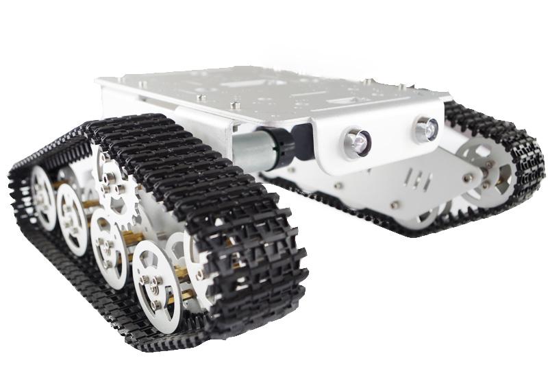
The T300 mounting instructions can be found here.
El T300 comes with 2 x DC motors wich encoders, which reference is DT25-370/9V11500-75K from DOIT, that is equivalent to the GM25-370 (Gear Motor, 25mm diameter)

Other chassis and motors can be chosen instead of these proposed. The requirement is to use 2 DC motors of 9-12V with encoders.
For this stage of the project we use only the power pins VM (black wire) and GM (red wire). The other four are for the encoder to be used later.
The chassis is usually sold with a controller (NODE MCU) that we will not use but install instead the power and control modules.
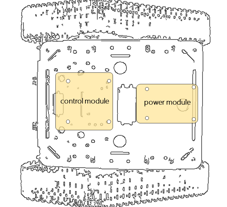
Power module
The power module is nothing more than a carrier of (1) a DC-DC converter from 9-12V coming from the battery to 5V that is required to power the control module, and (2) the H-Bridge that is used to power and control the DC motors.
It is pending the development of a PCB for this module so for the moment it must be mounted on a prototype board.
The mechanical design shown in the figure fits into the holes of the T300 chassis so no additional drilling is required.
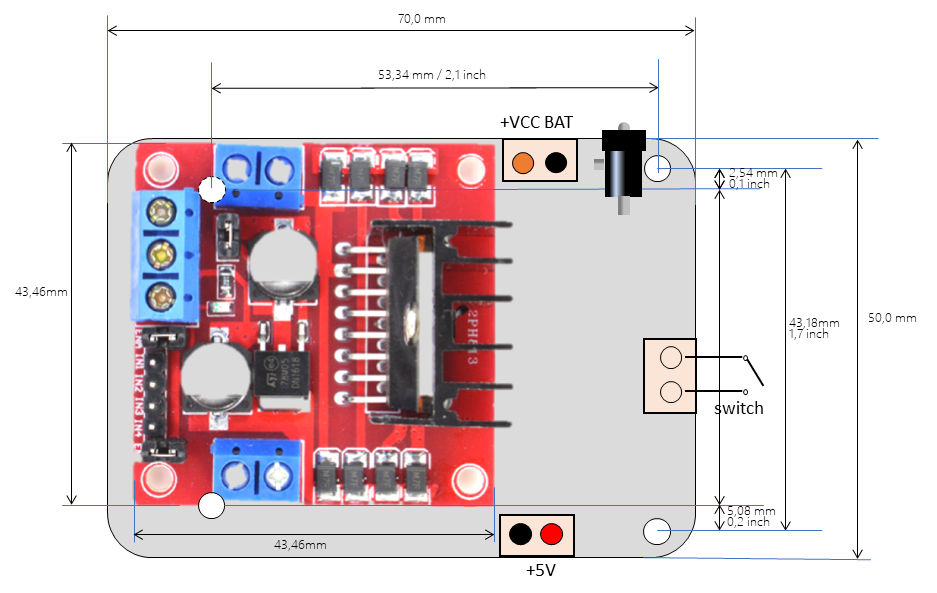
The following diagram shows how to perform the electrical connections (top view with the DC-DC Buck mounted on the rear side):
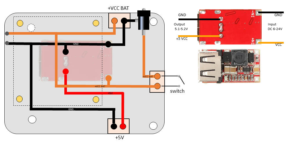
We are proposing a DC-DC buck with USB in anticipation that a device needs to be powered in the future. This is a valid alternative in case one without USB is preferred to save space.
Control module
The control module is a motherboard that carries a Raspberry Pi Zero and up to 4 boblock modules. For this first stage of the baseline configuration the mother board will hold the Raspberry and one single boblock in the motor slot.
The idea behind the boblock is to have independent functional modules as pieces that can be plugged and unplugged as needed. In this sense, the boblock works as some kind of LEGO block that allows building variants of the project over a common base. At the current time of the project development, 3 of these pieces are available: that of the motor controller for managing the H-Bridge and the encoders, that of the array of proximity sensors, and the one for the gyroscope. All of them run over the same HW but with a different SW.
The connectors of the sensor and motor cards are extended into the mother board so that devices are connected to the mother boards and not to the cards.
These are the connector on the mother board:
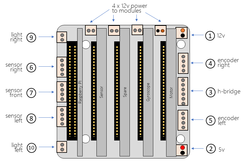
112V input, connected to the power module.
25V input, connected to the power module.
3connected to the H-Bridge in the power module.
4and 5are connected to the left and right encoders in the motors. These connectors are for the S1 and S2 inputs and to power the encoder circuit.
56and 8are connected to the HC-SR04 proximity sensors as is described later.
9y 10are connected to the front lights as is described later.
In addition, there are 4 connectors to power the boblocks with 12 volts if needed. Normally the cards will work with the 5 volts from the WBUS.
The manufacturing files of the mother board are available at GitHub for download.
Connecting the pieces together
Now we are ready to connect the modules together, and those to the motors and the battery.

The follwing are the connection needed for the baseline functionality:
1power input, connection to the battery.
2on/off switch.
312V power supply.
45V power supply (DC-DC bulk output to the control module).
5y 6motors power (connected to GM and VM pins).
7a 6 wires flat cable to the H-Bridge control.
Battery
The power input of the vehicle is the jack in the power module. The power source must be 7-12V DC. This input is connected to the DC-DC buck 6-24V input and to tge VM-GM pins of the motors.
The difference between the 9V expected by the motor and the 12V supplied by the battery is compensated by the voltage drop of the H-Bridge. In addition, the proposed power source is a 3-cell lithium (3S) battery whose nominal voltage is 11.1V.
This battery comes with a XT60 type connector so a cable adapter from XT60 to jack is required.


